 Generally speaking, I am a LEGO purist. I don’t cut, paint, glue, or modify LEGO elements. I think that working within the limitations of pieces forces creative solutions. There are circumstances for which I make limited exceptions and that is in the area of electronics. LEGO produces a very limited selection of wire lengths. Also powering electronics with batteries has been the only power solution for years. (As a toy company with an excellent safety record, I can’t blame them for the low-voltage-only stance). This solution is for a month-long show where battery power is impractical.
With the introduction of Boost, and the new Powered UP sets, the Power Functions (PF) line may be limited in life, but will likely remain a favorite of many adult fans of LEGO for a variety of reasons.
LEGO PURISTS: DO NOT PROCEEDED BEYOND THIS POINT!
This blog will get you most of the way there, however their goals are different from ours: which is simply to provide power to Power Function components from a common 9V wall transformer, the blog is for combining PF components to an Arduino board.
Materials

1 x LEGO Power Functions Cable Set 8886 or Set 8871
1 x 9 Volt AC to DC transformer (Wall Wart)
Solder
Electrical tape or heat shrink tubing
Tools (Required)
Soldering Iron
Wire cutters
Wire Strippers
Tools (Nice to Have)
Multi Meter
Scissors
Soldering hands
Magnifier
Utility knife
Anatomy of a PF Wire

Power Function wires are four conductor wires with a unique conductor at each end. In normal operation there is a positive wire, a ground wire, and 2 signal wires. These correspond to the four pins on PF connectors. If you look at the bottom of the light grey connector of the wire you will notice that it looks like a standard LEGO 2×2 plate with some metal on the edges. This configuration matches older LEGO battery boxes and wires (Mindstorms 1.0 and previous equipment roughly pre-2005).
Grabbing a trusty multi meter we can determine which pins correspond to which wires:

After a little testing the results of which I’ve sketched above the metal plates on the bottom of the light grey connector corresponds to the center two wires. We will connect the two center wires to the wall wart.
Part 1: Dissection
Using a pair of wire cutters snip the PF wire between one half and three quarters of the way from the connector you want to keep. I chose the keep the dark grey one. This way you have plenty of wire to work with but if you mess things up thoroughly you still have a chance with the other end.

Using a utility knife or wire cutters split the wire into the four component wires. The outer casing is the insulation it is not like an old telephone wire or an Ethernet cable that has an outer sheath with inner insulated wire.

Using wire strippers, remove the insulation form the middle two wires only.
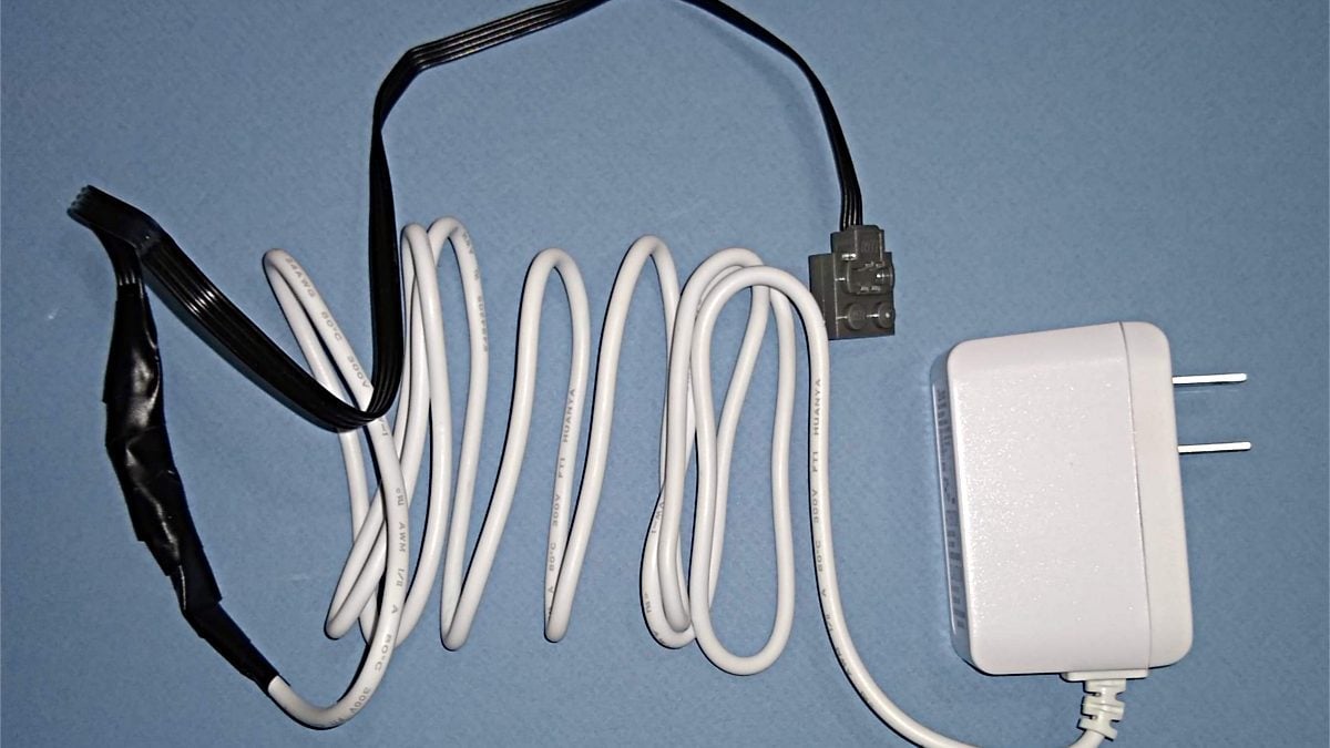
Then repeat these steps with the 9V transformer wire. You can cut very close to the connector. (Unless you are saving the connector for another use) In my case the wires were sheathed in an outer insulator (white) and insulated (standard red and black). You may find otherwise.

Part 2: Good Evening Dr. Frankenstein
Turn on your soldering iron and let it warm up.
**WARNING**
The usual tool safety rules apply. Soldering irons get very hot, they are also pointy. You should work in an area with good lighting, ventilation and away from flammable objects. Like working with a knife or a saw keep your eyes on the tool whenever it is in your hands, the second you lose track of the hot tip you will burn yourself. (Learn from my experience. Please!) Minimize distractions as well.
**WARNING**
Using electrical tape, secure the two outer wires of the PF Wire out of the way.
Next tin the four leads that will be connected. Tinning is the process of getting a small amount of solder on the components to be joined. This allows for the solder to flow more freely in the final joint and also minimizes big ugly solder blobs. To tin hold the tip of the soldering iron touching the bottom of the wire to be tinned, bring some solder in above the wire and hold until a thin layer melts and spreads along the surface.
Twist a wire from each wire together. How I did it end to end makes it hard to twist. (If you chose to use heats shrink tubing and go for an inline twist make sure you slide it on now.) If you twist them so they stick out in a cross shape your life will be easier. If you need the motor to spin in a certain direction test it now and switch the wires if needed. It is however just as easy to include a PF switch, or place an idler gear in the system to correct rotation.
Bring the soldering iron in contact with the twisted and tinned leads, some more solder maybe required to form the joint. Repeat with the other lead.
Test system with a multi meter of plugging it in. Unplug/disconnect multi meter. Re-solder if necessary. Try to avoid large blobs of solder.

Cover any exposed leads with electrical tape or heat shrink tubing. Repeat for the exposed length for protection and strength.

Part 3: IT’S ALIVE
The transformer used in the hack I did has a slight delay in powering up from the moment of plugging in. Likely lag in the transformer coming up. This is not of importance to me as the build is for a long term continuous operation. If you need instantaneous power a switch after the transformer should take care of this slight lag.


Good information.
Personally, I would have used a NASA / AT&T-style splice. It makes a bigger bump, but it doesn’t require soldering skills.
https://makezine.com/2012/02/28/how-to-splice-wire-to-nasa-standards/
Another option would be to use small crimp-on butt-joint connectors.
I like to stagger the joints and heat shrink each one before putting a heat shrink jacket over the whole joint area.
Matt,
Awesome info thanks for sharing! I will definitely be adding that splice to my tool box.
I don’t understand why, if the outer of the four wires are + and GND, why you connect the middle wires which, to my understanding, are control wires (signals to speed up/slow down motors)?