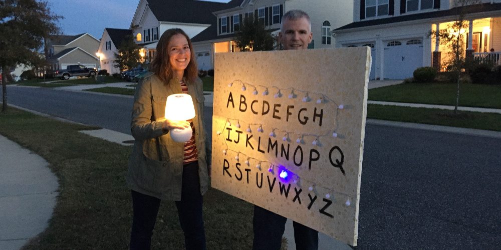
For Halloween 2016, I made a portable Stranger Things Ouija wall that spelled out messages as I carried it around the neighborhood. My wife went as Joyce, and I was pretty hopeful that our costumes would be well received. Unfortunately, most of our neighbors hadn’t seen the show at that point, and the overwhelming consensus was that I had dressed up as “the alphabet.”
What a difference a year makes! With the incredible popularity of the show this year I thought people might be interested in how to make their own Stranger Things wall. Most of this article will focus on the electronics, wiring, and software, as the construction of the frame was a relatively simple affair by comparison.
Parts List
Many of the materials I already had sitting around, particularly for the electrical components. Feel free to substitute with what you know, or bulk hobbyist kits with an assortment of parts.
- Sheet of ¾” plywood or other convenient wood scrap for the frame.
- Spray-on glue, can.
- Construction adhesive, tube.
- 4′ x 3′ laminate sheet or similar material.
- String of LEDs (this is what I bought)
- Battery cases and connector snaps.
- 100′ black wire; 100′ red wire.
- 2x 16:1 Analog Multiplexers (DG406DJZ)
- Breadboard (such as this one, but the specific model doesn’t matter)
- Breadboard wires (I recommend spools and cut to fit, but you can buy jumpers if you prefer)
- Raspberry Pi
- This is a compact linux-based computer that used to control the lights.
- The specific model shouldn’t matter as long as it has accessible General Purpose Input/Output (GPIO) pins.
- If you know what you’re doing or want to experiment, feel free to use an Arduino or other hobbyist board.
- Resistors, LEDs, and potentiometers (here’s a mix pack)
- 2x 47μF capacitors (hard to buy singly, but you could try Digi-Key. Here’s a mix pack)
- 5V Voltage Regulator (I used a 7805, but could probably use a bit more current. Try the 78S05.)
- Diode, 1N4004
Tools
You’ll need a saw, drill, tape measure, staple gun (or tacks and hammer), pliers, wire cutters, wire strippers, and a soldering iron (with solder). I found clamps very useful in assembling the frame. Having a multimeter on hand may also be helpful.
Building the Frame
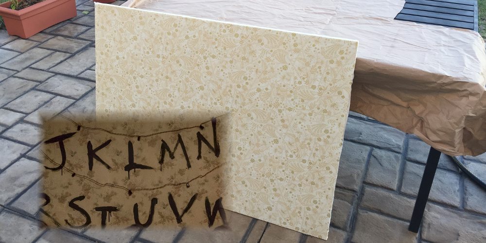
I needed something that would be sturdy, yet light enough to carry around. I decided to build the frame out of ¾” plywood which I cut to 1″ wide on a table saw. Since I wasn’t setting out to create a perfect scale model, I sized the frame members to make the wall roughly 3.5′ x 2.5′, with a vertical cross-piece for extra support. I’d like to tell you I did something fancy to put it together, but all I used was white glue and butt joints with wood screws.

Once it was built, I toyed with attaching fabric directly to the frame, but determined it wouldn’t be sufficiently sturdy to hold up the lights. Fortunately, I had some spare laminate sitting around, which I cut to size and glued to the frame using construction adhesive. It was a perfect material, being both light, but also rigid when attached to the frame.
For wallpaper, my wife went on an epic fabric hunt and found a surprisingly close match. We cut it to size and used spray glue to adhere it to the laminate, with staples attaching it to the frame on the back side. Note that this didn’t stick anywhere near as well as I had hoped; I probably should have roughed up the laminate with sandpaper before gluing on the fabric.
Attaching the Lights
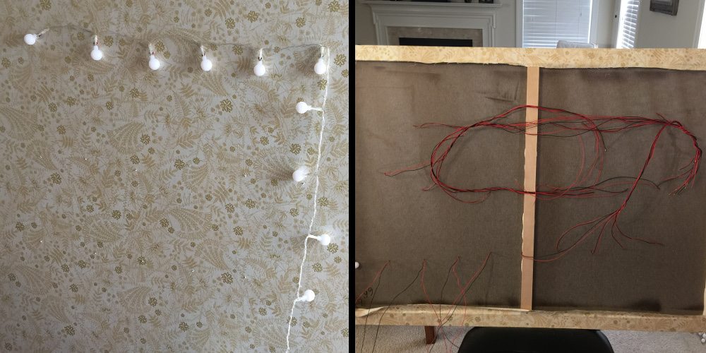
Fortunately, we’ve moved on to the era of LED Christmas lights, as this greatly reduced the portable power I would need to carry. The set I bought turned out to have three wires: one ground with two carrying power to every other light, so that it could blink them in alternating sequences. In the end, this actually proved somewhat helpful as it provided additional support along the string even as I cut LEDs to isolate them from the rest of the lights.
LED stands for “Light Emitting Diode,” which means these lights don’t function like regular incandescent bulbs. The polarity matters – electricity will only flow in one direction. You also need to ensure you have a resistor in the circuit as LEDs will burn out without one.

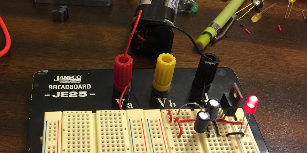
To wire up the lights, I set up a 4xAA battery pack to provide 6 volts and a connected it to a 220 Ohm resistor (red-red-brown) on the breadboard. One at a time, I cut each LED away from the string and used a soldering iron to melt the plastic housing to access the wire contacts at its base. I’d then attach the batteries to verify which side of the LED needed to be connected to the positive terminal. Once I knew the polarity, I soldered on a long lead of red and black wire, respectively to the positive and negative terminals. Every few lights, I drilled a hole into the wall and fed the wire leads through.
With all the wiring through, I could focus on the next question: how to control the lights so I could light them up one at a time. While you might think that I could simply connect each light to a pin on the Raspberry Pi, there are a few problems with this approach:
- The output voltage of a Raspberry Pi is only 3.3 V and likely insufficient for this task, depending on your lights.
- If you accidentally short out a pin by driving a light without resistance, you can damage your Pi.
- With 26 lights to drive, it would use most of the available pins on the newest Pi models; my older version had only 17 pins available.
What I needed was a way to drive 26 lights safely, using just a few connections. This is where multiplexers come in!
Multiplexers
If you already understand multiplexers and demultiplexers, you can skip this part.
A multiplexer is a way of routing one of many inputs to a single output. This allows for a sharing of resources. Think of old-school telephone wiring: a number of telephones in a building could be routed to a single output line to save on external connections, with the drawback being that only one phone can talk outside of the building at a time.

What I needed for the Ouija wall was the opposite: to take one input and route it to one of the many letter LEDs. This is a demultiplexer. The question is: how do you choose which letter is being lit up? For this, you need to use a few pins to tell the demultiplexer which output wire you want to select. Let’s pretend I only need letters A to H. I can select which one to light up using just three pins from the Raspberry Pi.

In this figure, the truth table on the right shows how to connect input D to any individual LED. Connections A2, A1, and A0 (A for “address”) can be driven low (0 volts) or high (3.3 volts) by the Raspberry Pi output pins to make the selection.
You might wonder what happens if I don’t want any of the lights on. That’s what the enable pin, E, is for on the demultiplexer. When it’s driven low, input D is completely disconnected from all of the outputs, so no LEDs will be lit.
Digital multiplexers and demultiplexers don’t actually form a “connection” from the input to the output – it’s a logic operation, where a high input or low input is replicated on the output. For this project, I needed an analog multiplexer which physically connects the input to the output. When looked at like this, analog multiplexers and demultiplexers are really the same device, and simply referred to as multiplexers.
The DG406 Analog Multiplexer
Multiplexers are usually available with connections in powers of two, meaning 2, 4, 8, 16, 32 (etc…) outputs. They get more expensive as you add more connections, and the only reasonable choice I found for this project was the DG406, which supports 16 connections. You can read all about how it works in its reference sheet. Here’s two ways of looking at the chip:
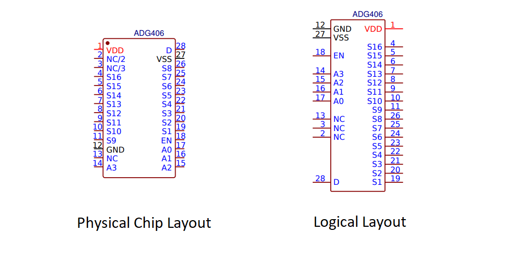
The physical chip layout shows where the pins are on the chip as if you were holding one in your hand. You need to know this information when connecting wires, but it can be a bit of a mess to make a circuit diagram with the physical layout. Instead, I’ll be using the logical layout as shown on the right. Here’s what the various connections are:
- VDD: Connect this to the project’s source voltage.
- VSS: Also called V-, for this project it is connected to ground (zero volts).
- GND: Connect this pin to ground.
- D: The input pin. This will be connected to our source voltage through a resistor and will be used to power the LEDs.
- A0 – A3: The address lines to select which output pin is connected to D.
- S1 – S16: The 16 output pins.
- EN: The enable pin. When low, all outputs are disconnected. When high, the active output is selected by the address pins A0-A3.
- NC: No connection.
Connecting to the Raspberry Pi
Since the Stranger Things Ouija wall needs to be portable, I required a stable power supply that could power the Raspberry Pi at 5V. For this, I used a circuit from BASIC Stamp 2 Tutorial and Applications by Peter H. Anderson, a book I bought along with a BASIC Stamp quite some time ago.

Anderson explains that the purpose of resistor R1 and the LED is to provide a quiescent power supply; it also shows you that your power is on. Capacitors C1 and C2 help the circuit respond to momentary increases in current draw, providing a more stable output. I won’t go into other details on the circuit other than to warn you that the diode (D2) and capacitors have polarity requirements; make sure you connect their terminals correctly.
The circuit to connect to the Raspberry Pi uses an approach very similar to the demultiplexer example. However, as the DG406 only has 16 outputs and there are 26 letters in the alphabet, I needed two of them, connecting LEDs A..P to the first and Q..Z to the second. The approach here is to share the address lines. So, if A0 to A3 are all set to low, D would be connected to S1 on both chips. Since this would light up both letters A and Q simultaneously, the solution is to connect two pins from the Pi, one to the Enable pin of each DG406, and control them such that at most only one multiplexer is enabled at a time.

The Raspberry Pi header layout shown here matches the physical connection of my board; yours may differ. The purpose of the R2 variable resistor is to allow the adjustment of the total amount of resistance in the circuit to the lights, allowing me to vary their brightness.
Since the DG406 has 16 outputs it requires 4 address lines to select which output is connected to D (24 = 16). Here is the full truth table, using L and H for low/high to make it easier to read:
| E (GPIO 24) | E (GPIO 23) | A3 (GPIO 22) | A2 (GPIO 27) | A1 (GPIO 18) | A0 (GPIO 17) | LED |
| L | H | L | L | L | L | A |
| L | H | L | L | L | H | B |
| L | H | L | L | H | L | C |
| L | H | L | L | H | H | D |
| L | H | L | H | L | L | E |
| L | H | L | H | L | H | F |
| L | H | L | H | H | L | G |
| L | H | L | H | H | H | H |
| L | H | H | L | L | L | I |
| L | H | H | L | L | H | J |
| L | H | H | L | H | L | K |
| L | H | H | L | H | H | L |
| L | H | H | H | L | L | M |
| L | H | H | H | L | H | N |
| L | H | H | H | H | L | O |
| L | H | H | H | H | H | P |
| H | L | L | L | L | L | Q |
| H | L | L | L | L | H | R |
| H | L | L | L | H | L | S |
| H | L | L | L | H | H | T |
| H | L | L | H | L | L | U |
| H | L | L | H | L | H | V |
| H | L | L | H | H | L | W |
| H | L | L | H | H | H | X |
| H | L | H | L | L | L | Y |
| H | L | H | L | H | L | Z |
| L | L | – | – | – | – | None |
| H | H | Do not do this – two letters would be lit simultaneously. | ||||
GPIO pins 23 and 24 from the Raspberry Pi are used to control which multiplexer is enabled, with GPIO 23 controlling the lower bank (letters A through P).
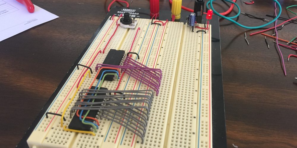
The circuit is sufficiently complicated that I wanted a very neat breadboard layout to help avoid mistakes. I brought all of the outputs to a consecutive set of locations on the breadboard to make it easier to see what I was doing.
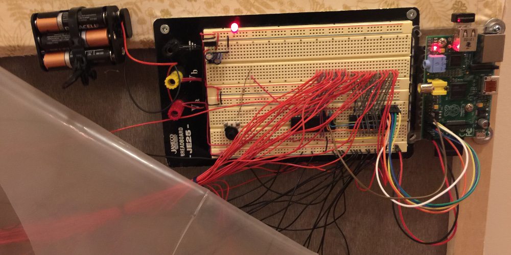
After mounting the batteries, breadboard, and Raspberry Pi to the back of the wall, I then plugged in the connections to the LEDs, and connected the breadboard components to the Raspberry Pi using flexible jumper cables.
Choosing the Right LED in Software
If you’re comfortable with Python and bitwise operators, or don’t really care to know the details, feel free to jump to the software.
I won’t be going over how to configure your Raspberry Pi here. If you’ve picked one up, there are any number of tutorials out there that explain how to connect to and program your Pi using Python. However, I did want to discuss how to turn a letter into the matching set of pins to light up the correct LED.
Let’s say the letter we want to light up is a lower case “L”. How could we light the correct light? One way would be to use a series of if statements to set the pins as per the above truth table. The code for a particular letter might look like the following:
if char == "l":
    enable_low_bank = GPIO.HIGH
    enable_high_bank = GPIO.LOW
    a0 = GPIO.HIGH
    a1 = GPIO.HIGH
    a2 = GPIO.LOW
    a3 = GPIO.HIGH
That’s clearly going to be a nightmare – there will be 26 copies of this block of code, one for each letter. Instead, we can take advantage of the fact that the index of each letter (counting from zero) matches the address of the pins needed to light that letter when treated as a binary number:
| Letter | Index | a3 | a2 | a1 | a0 | Binary |
| A | 0 | 0 | 0 | 0 | 0 | 00002 |
| G | 6 | 0 | 1 | 1 | 0 | 01102 |
| L | 11 | 1 | 0 | 1 | 1 | 10112 |
| P | 15 | 1 | 1 | 1 | 1 | 11112 |
Given that, all we have to do is to make the output pins match the binary value for letter’s index. First, convert the letter to a number from 0 to 25. Each character actually has an underlying numeric value defined by what character encoding is being used (ASCII or Unicode are examples). By subtracting the numeric value for ‘a’ from the character we’re lighting up, we’ll get a number from 0-25. Here, we can use the function ord(), which returns the encoded value for a letter.
char_index = ord(char)-ord('a')
So now we have a value, recorded in char_index, ranging from 0-25. How do we get each bit of the binary equivalent? For this, we use bitwise operators. The first is the AND (&) operator, which operates on corresponding bit locations of two numbers. Wherever they are both 1, the result is a 1. If a bit in any position is 0, the corresponding result bit is also 0.
The other operator is a bitwise right shift. This takes the bits of a number and moves them to the right by a given number of positions. Positions on the left are filled with zeros. Here’s the number 13 (11012) being shifted to the right by 1, 2, 3, and 4 bits, respectively.

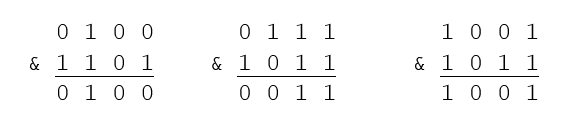
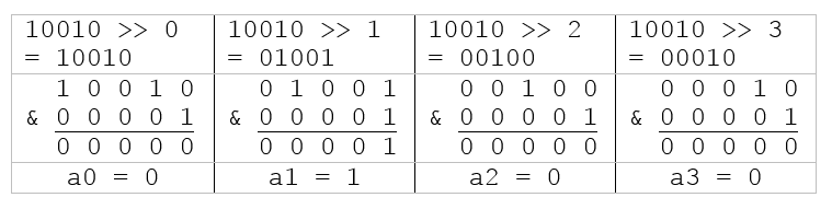
With these two tools we can obtain the bits for the address of the correct LED to light. Here’s an example using the letter L, which is character index 11, binary 10112.

To get each bit, shift the number to the right based on if you want the zeroth, first, second or third bit, and then perform a bitwise AND with 00012 to isolate just that bit.
At this point, you might be wondering what happens with letters beyond P (16 to 25). This doesn’t pose any difficulty. These letters just require five bits to represent them. But, because we use a bitwise AND operator, that extra bit will be filtered out. Here’s an example for letter S, index 18, binary 100102:
The section of my program that extracts the binary addresses combines the shift and bitwise AND into a single line, taking advantage of Python’s ability to iterate over an array (of the pin addresses) while also providing a count as it loops. Note that the function GPIO.output(pin, value) is used to drive the specific pin high or low.
#pin definitions
a3 = 22 #Broadcom pin 22; Gen3, Pi pin 15
a2 = 27 #Broadcom pin 27; Gen2, Pi pin 13
a1 = 18 #Broadcom pin 18; Gen1, Pi pin 18
a0 = 17 #Broadcom pin 17; Gen0, Pi pin 11
address_pins = [a0, a1, a2, a3]

#.. ~~~snipped lines for clarity in example.~~~

    for pin_number, pin_address in enumerate(address_pins):
      GPIO.output(pin_address, char_index >> pin_number &1)
The assumption I’ve made here is that GPIO.LOW is 0 and GPIO.HIGH is 1 (or at least non-zero). It’s a reasonable assumption, but my code could break if those definitions were changed in a later release. This program isn’t important enough to design with that in mind.
Finally, since the design connects the same address lines to each DG406, all we have to do is to manually decide which DG406 to enable. If the letter is A-P we enable only the lower DG406, and if Q-Z, we enable only the higher one.
The Software
After setting up the GPIO pins for output, my program repeatedly calls the blinkMessage() function, sending each word to be displayed, and sleeping for an amount of time between every word or phrase. The function blinkMessage() takes care of enabling the correct address pins, as discussed above. Here is the entire program:
import RPi.GPIO as GPIO
import time

#pin definitions
a3 = 22 #Broadcom pin 22; Gen3, Pi pin 15
a2 = 27 #Broadcom pin 27; Gen2, Pi pin 13
a1 = 18 #Broadcom pin 18; Gen1, Pi pin 18
a0 = 17 #Broadcom pin 17; Gen0, Pi pin 11
e1 = 24 #Broadcom pin 24; Gen5, Pi pin 18 #e=enable, used for select DG406.
e0 = 23 #Broadcom pin 23; Gen4, Pi pin 16

#Group outputs in array for easy looping and configuration.
output_pins = [a3, a2, a1, a0, e1, e0]
address_pins = [a0, a1, a2, a3]

#This function takes in strings to be printed, and displays
#them to the Ouija wall letter by letter.
def blinkMessage(display_str):

  display_str = display_str.lower()  #Convert string to lower case.

  for char in display_str:
    char_index = ord(char)-ord('a')  #Get the relative character nubmer (a=0 b=1 etc)
    if char_index < 16:              #Choose the correct bank to turn on.
      low_bank = GPIO.HIGH
      high_bank = GPIO.LOW
    else:
      low_bank = GPIO.LOW
      high_bank = GPIO.HIGH

    #Convert the char_index to a binary nuber, one bit at a time
    #and set each pin output to high or low (based on 0 or 1 for the bit)
    #Based on GPIO.LOW being 0 and GPIO.HIGH being 1.
    for pin_number, pin_address in enumerate(address_pins):
      GPIO.output(pin_address, char_index >> pin_number &1)

    GPIO.output(e0, low_bank)  #Turn on banks as last step to avoid momentary flashes.
    GPIO.output(e1, high_bank)

    time.sleep(0.5)            #Display the LED for half a second.
    GPIO.output(e0, GPIO.LOW)  #Turn both banks off to turn off all LEDs.
    GPIO.output(e1, GPIO.LOW)
    time.sleep(0.15)           #Keep all LEDs off for a moment between each letter.

#START OF MAIN PROGRAM

#Configure the pins for output, and set them all low to start.
GPIO.setmode(GPIO.BCM)   #Indicates we're using GPIO number for pin identification.
for pin in output_pins:
    GPIO.setup(pin, GPIO.OUT)
    GPIO.output(pin, GPIO.LOW)

#The main program loop; prints messages over and over.
try:
  while 1:
    blinkMessage("Help")
    time.sleep(0.5)
    blinkMessage("Me")
    time.sleep(3)
    blinkMessage("Demogorgon")
    time.sleep(0.5)
    blinkMessage("Run")
    time.sleep(3)
    blinkMessage("HappyHalloween")
    time.sleep(3)
Wrap-Up
Here’s the wall out on Halloween:
Phew! That was a lot more depth than I anticipated. It makes me wonder if the wall on Stranger Things was done with manual switches or even with CGI magic. Hopefully you’ve found something to use here in your own projects. If you need any help with working with any of the concepts I went over here, or if this project inspires you to create, feel free to hit me up on Twitter.