While writing projects are in full swing, I often tend to collect small DIY projects that remain stacked on shelves until I have some of that free time… I’ve recently finished up writing two books that are now heading to the printer, and I find myself with some free time. I should be putting together a proposal for my next book, but instead I’ve reached for a small box of parts. To quote one of my favorite movies:
It’s yet another in a long series of diversions in an attempt to avoid responsibility.
This past weekend’s project was quick and simple (relatively speaking), and I had a very easy gauge for determining its success or failure … would I be able to play the classic Atari 2600 game, Adventure, as it was meant to be played?
And by that, I mean played on a large 50+” LCD screen, from the comfort of my couch, without having to find some crazy TV converter for the actual 2600 I have tucked in a box in my basement?
The Bluetooth Arcade Stick kit was simple enough. It came from Adafruit, and the real power behind it is the Bluetooth EZ-Key Keyboard Controller. Adafruit sells all the components you need to make it with the exception of the wooden box that I ordered from Amazon (based on Adafruit’s online provided part description). Below you can see all the components with the exception of the 3-AAA battery holder, batteries, and wire.

The instructions provided by Adafruit are good, but there are some holes… so I’m going to go over the assembly quickly and point out some areas that managed to give me pause and force me to do some thinking and, in one case, make a short drive to the nearest Radio Shack. Keep in mind that total time to build this thing was about an hour not counting painting time and the drive to The Shack.
Per the instructions, you can wire up most of the kit using a standard breadboard just to test everything out. You’ll want to identify the wires on the joystick that pertain to Up, Down, Left and Right. Just use a multimeter to test each wire and be sure to label the wire or create a wiring diagram like the one below. (Note that my wire colors and order differ from the Adafruit instructions, so you’ll definitely have to test this on your own — don’t go by my diagram or Adafruit’s… your joystick could be slightly different.)
 Next, solder up the EZ-Key device. On a scale from 1-10, with 10 being difficult, I’d give this a 3 or 4. You’ll insert the provided headers into the device, but you really don’t need to solder up all 24 pins. I only needed to solder 11 of them — pins 0 through 6 for the four joystick wires and three buttons, and all three GND connectors and one Vin (Voltage In). The soldering is fairly forgiving, so it’s fine for a kid who needs some soldering practice (or an adult). I inserted the headers into a small breadboard and then dropped the EZ-Key over the headers… the breadboard holds the headers perfectly upright and stable, making it easier to solder.
 After soldering up the EZ-Key, it’s time to test the joystick before moving forward. Insert the EZ-Key into a larger breadboard, connect a power supply to it, and add some jumper wires to connect power and GND to the EZ-Board. At this point, I didn’t wire up the buttons, and the instructions don’t have you do this either. The main thing you’ll want to check is that the EZ-Key can communicate with your laptop or computer via Bluetooth AND that the joystick will move a cursor left, right, up and down.

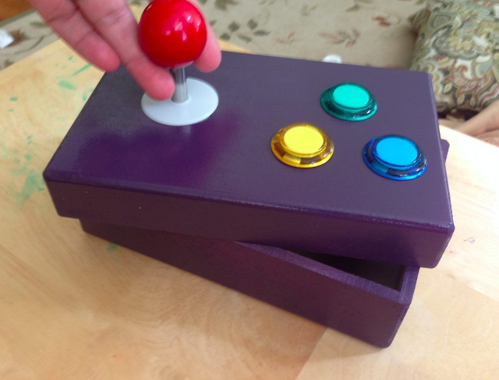
After the EZ-Key connected, I opened an Excel spreadsheet and verified that the joystick would move the cursor left, right, up and down… worked great. At this point, the instructions focus on preparing the box to hold everything. I marked the best location for the joystick and three buttons (plus a power button that will go on the back of the box) and drilled it all out in about five minutes.

My last task for Friday was painting the box and applying some coats of lacquer. I went with purple because it was the can that held the most paint.

Saturday, I picked back up in the afternoon with test fitting buttons. The holes for the buttons are drilled at 1-1/8″ diameter but you’ll never get them in. If you don’t own a round file, spend the $2-3 because it beats trying to sand down the hole edges using flat sandpaper. Five to six spins around each hole with the round file and the buttons fit snug with no movement.

I hate soldering wires to headers. Hate. It. Fortunately, Radio Shack has you covered. For about $5, you can buy a set of ten wires that fit perfectly on the headers you soldered on the EZ-Key. The Part # is 2760151.

Here they are inserted onto the EZ-Key. These wires are very flexible, and you’ll see shortly that they can be routed as needed inside the box.

I ultimately ended up doubling up the black wire from the joystick and the daisy-chained black wires from the buttons into a single one of these special header-friendly wires. I was using solid core wire for buttons so those inserted easily. The joystick’s wire was braided so you have to be careful inserting into these special wires — I used electrical tape to secure all wires. After connecting the joystick wires, I once again applied power and tested all the connections with my Excel spreadsheet to make certain those connections were good. Everything worked, so on to the buttons.

If you look at the photo above, you’ll see that I’ve already soldered a series of black wires to daisy chain the three buttons. Starts at blue and ends at green, with another black wire free and ready to be connected to one of the GND pins on the EZ-Key. Each button will also have another wire (red in photo below) that is soldered to the other connector on each button and then wired up to ports 4, 5, and 6 on the EZ-Key. (These correspond to Return, Space, and 1 keys on a keyboard — many games will use these as Shoot, Jump, and P1 Start.)

You can see the Power button to the box in the photo above. The power supply will have the red wire soldered to one connector… and another wire goes from the other connector to the Vin port on the EZ-Key — this lets you turn the box on and off, saving battery power.
It’s a bit ugly in the photo below, but you can see that I’ve finished up adding the power supply (3-AAA batteries) and tucked all the wires around the joystick. The EZ-Key is very light and almost floats wherever you place it. I may choose to secure it later, but for now it’s not got a final location. The battery holder is secured to the side with Gorilla Tape.

Next, I sealed up the box with thin strips of velcro on all sides… and then it was time to put it to the test. I fired up Stella on my MacBook Air, configured it for Full Screen Mode, and then flipped the MacBook to my TV via AirPlay and the AppleTV device — you could just as easily do this with the ChromeTV device.
I opened up Adventure, selected Level 3, and went to battle dragons. Three of them — Red, Green, and Yellow. The joystick worked great, and the Space button allowed me to drop items.

My boys enjoyed playing some classic Atari games on the big TV, and I enjoyed watching them play the games I spent hours and hours and hours mastering — Yars’ Revenge, Pitfall, and so many more.

And yes, it works great with MAME. Not all games, of course, but the classics work perfectly — Pac-Man, Asteroids, Space Invaders, Galaga, Gorf… the list goes on. I did have to go in and modify the controls a bit for some of the games so they recognized the various buttons, but it works perfectly.
No wires, Adventure from the couch, and less than two hours of time invested. Given more time, I probably could have come up with a few additional tweaks such as a nicer case, more buttons, etc… but all I really wanted was a way to play some classic games with my boys in the living room on the big screen… mission accomplished.
Again, the Adafruit instructions are good, but expect to find a few holes in the documentation. For example, the On/Off power button requires a 5/8″ hole, and there’s not much detail provided for wiring up the large breadboard for testing — some basic electronics knowledge is sort of expected. Still, with some patience and close examination of the Adafruit photos (and mine), you should be able to figure things out. I’m going to include some more closeup photos here that might help you should you choose to try building your own… good luck!


thx for another great idea.. we love this stuff.
It’s a really fun project and Adacruit made it easy by putting all the components on the instruction page (except for 3-AAA battery holder). I just also figured out how easy it is to flip it for a right hand joystick control – just swap out the wires for the headers on the EZ-Key and done.
I’m not too familiar with using a multimeter… how exactly will it show me the corresponding direction for each wire from the joystick? I’ve not yet to start this project, still reading up on some of the things I’ve never worked with before.
Multimeters can be switched to a short-circuit checker mode when they beeping if the two leads are connected. So you have to connect one of the leads to the common (GND – I suspect it will be the black) wire of the controller and the other to one of the other 4 wires. Then turn the stick to activate one of its switches and if you are measuring on the correct wire the multimeter will beep.
can you add 5 more buttons?
Nice project. I have just ordered the parts for a similar controller but I am planing to put it into a lower-profile box.
I just wish I could get a hold of one of those EZ-key controllers! Out of stock everywhere, and no reasonable alternative (other than hacking a bluetooth gamepad, which is unreliable at best when I tried it) Great work!
Hi, James. My name is Marcos Ravena and speak from Brazil.
This project is so awesome! Simply beautiful.
Can I ask something!?
Do you made some test on a Apple TV 4ª generation or iOS devices?
Other question: If I need remap the buttons (in case of controller don’t respond the respective commands of the game), do you would know how to make it!?
I’m thinking about build my own controller to use with my Apple TV 4ª Generation. The new and old work together. It would be amazing!
I just love this type of work DIY.
Best regards!